
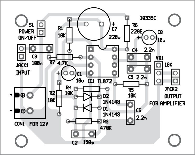
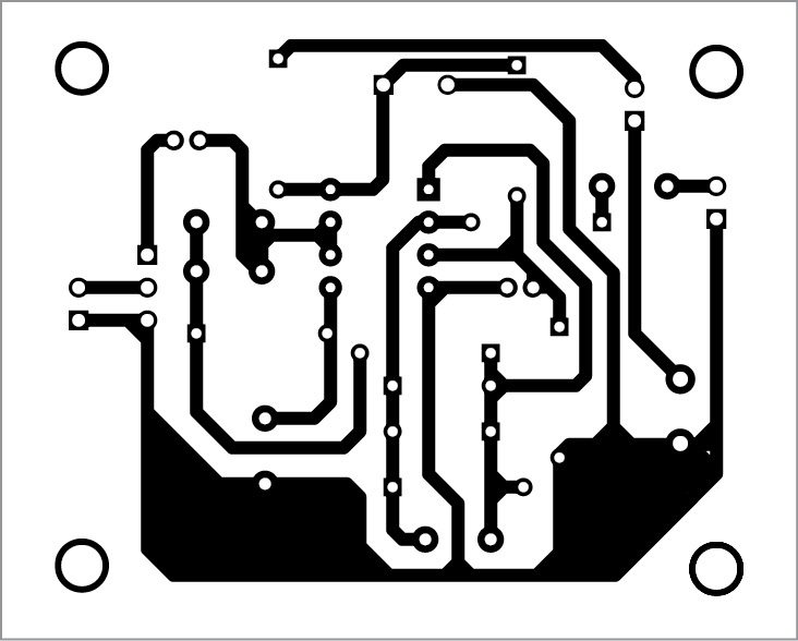
Layout Pcb Compressor Limiter
We classify the l2m as a mastering limiter because it was designed with the specialized requirements of the mastering. Answered jul 15,2021 by charles o'neal;
Layout Pcb Audio Limiter PCB Circuits
The cv generation for the vca is pretty standard.

Layout pcb compressor limiter. Design is based on that corp. In it's 12th year of production, the l2m is an optical limiter based on classic designs of the early 1960s and is the beneficiary of many significant improvements, representing what a truly refined optical limiter can be. Anyone have an audio compressor limiter pcb layout?
Rare vintage original pcb from late 1960s audio & design (recording) adr f600 limiter. A true rms converter is used in the side chain while the gain element is an all discrete. Audio limiters can be used in a transmitter schematic or in any circuit you need a constant audio level.
If you can build an enclosure with power, i/o, pots, and a meter, you'll have a working f600 limiter! Reduction led which lights when signal level exceeds treshold. Both the guitar and bass versions were originally traced by aion fx in 2017.
310 pcb's layout design ideas in 2021 | electronics circuit, layout design, audio amplifier headphone/audio amplifier circuit on pcb using lm386 pira cz compressor/limiter/clipper for fm broadcasting Supports jpg, jpeg, gif, png, bmp. Adjustable by potentiometers treshold, ratio, attack, release, makeup gain.
The parts list for the 1176 Some compressor clutch circuits contain a thermal limiter switch that senses compressor surface temperature. Anyone have an audio compressor limiter pcb layout?
Log in to post comments. Drip brings you the 1:1 design after a year of work taking on the challenge to bring this rare bird. Rightclick the link and select "save as." note:
Treshold and makeup can be controlled by cv. They monitor the temperature of the vapor coming out from the evaporator core and sends a signal to the thermal limiter if the temperature of the vapor gets too high activating a circuit that will shut down the hvac compressor. The 1176 has been employed in countless recordings over the years and it is still used by almost every recording studio.
The superheat switch and thermal limiter fuse protect the compressor against loss of refrigerant and oil. The audio signal flows unaffected through ic1a/b. When the audio input level is between 20mv and 20v the output will be a constant 25mv signal.
235 views [pcb] how to identify sensor if on a pcb. Foreword text emphasis note caution warning this manual contains all the information you need to operate the 525 gated compressor,'limiter. Wiring diagram (with millennium bypass) before populating the pcb you can use it as a drill template by poking a pen through the holes where the pots are.
In the usa the setting should be 75us and for the rest of the world the setting should be 50us. Each file cannot exceed 2mb. The drip design of the classic and out of reach u73b compressor limiter is an amazing feat of layout achitecure and electrical engineering.
Drip brings you the 1:1 design after a year of work taking on the challenge to bring this rare bird. The audio & design f600 was introduced in 1966, making it the very first solid state limiter! You can only upload 1 files in total.
This is the complete circuit taken from an original f600. 1:1 circuit of the 1968 la2a schematic. This audio limiter circuit is easy to build, works with ba741 8pins or 4pins so pay attention and uses a symmetrical power supply.
The drip design of the classic and out of reach u73b compressor limiter is an amazing feat of layout achitecure and electrical engineering. The signal level to subtract is regulated through a sims vca. Good dayplease i want to trace a fault on an s2 board controlling an ncr s2 machinehow do i identify a sensor ic that control the divert.
This is a feedforward vca compressor. Software design photo gallery guestbook ebay store. Front panel pcb makes wiring the entire.
The urei 1176 peak limiter is a classic audio compressor designed by bill putnam, first built in 1967, making use of fets and using them as a variable resistor to control the gain reduction in the circuit. Model 525 dual gated compressor / limiter operating manual revision 3.0 10 february, 1989 4211 24th ave. The limiter compressor circuit operates the audio gain around a fast attacking limiter in conjunction with a gentle agc.
It looks like you have not written anything. Back to life, it was drips intention to keep the entire design as accurate as possible , we contacted sowter transformers to design us the new.

Skema Audio Compressor Limiter File Ini

Layout Pcb Audio Compressor PCB Circuits
Layout Pcb Audio Compressor Pcb Circuits

Layout Pcb Audio Compressor PCB Circuits

Skema Audio Compressor Limiter File Ini
+Limiter+Pira+CZ.GIF)
Karya Solderanku Untuk Brokesan FM

Audio Compressor Limiter Circuit AUDIO BARU

Layout Pcb Audio Limiter PCB Circuits

Layout Pcb Audio Limiter PCB Circuits

Audio Compressor Limiter Schematic AUDIO BARU

Diagram Layout PCB dan Schematic Dyna & Ross Compressor
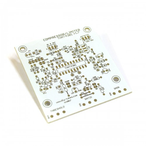
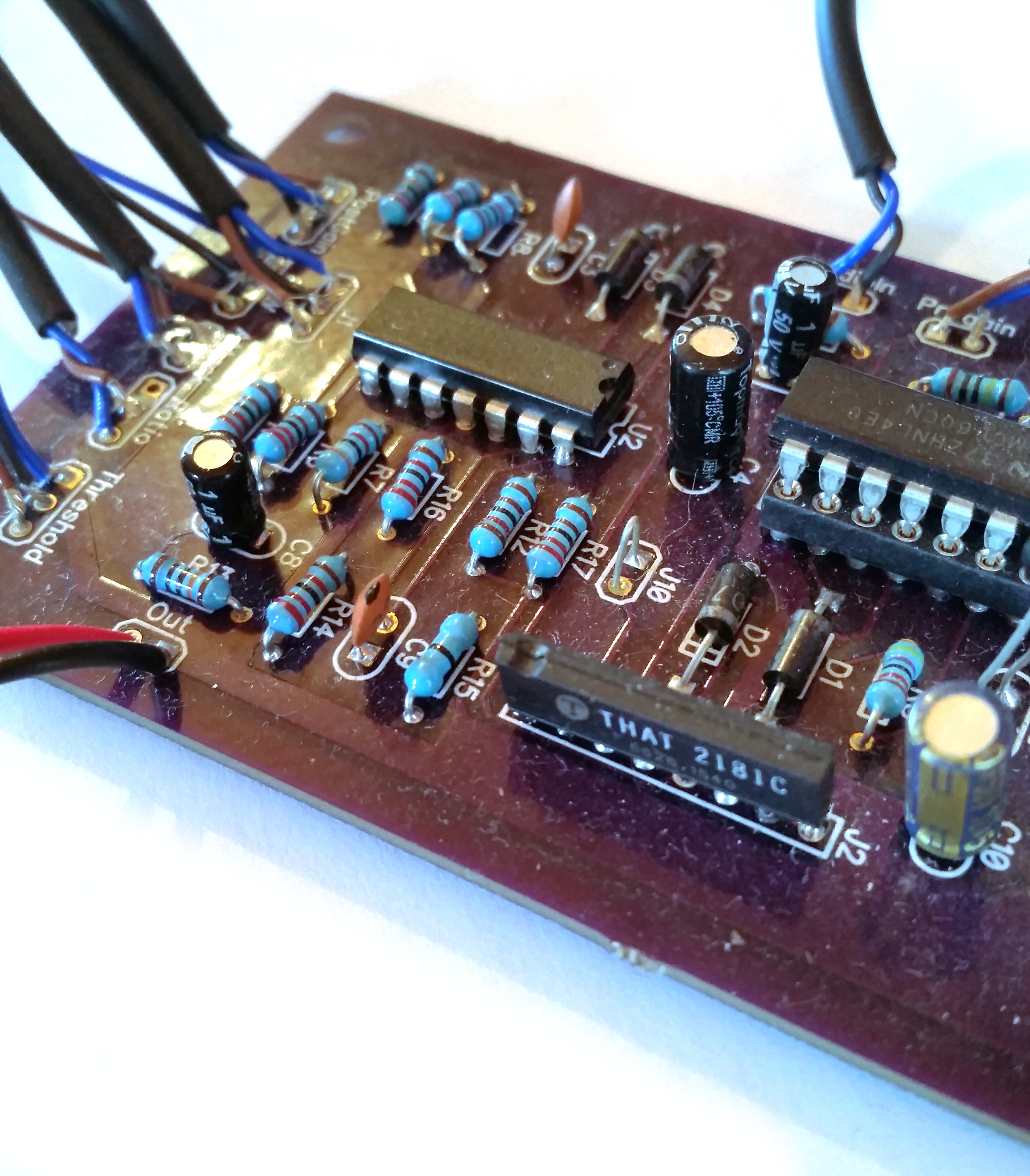
THAT4301 Compressor/Limiter PCB v1.7
Layout Pcb Audio Compressor Pcb Circuits
Analog Compressor Design Matt Rottinghaus

Compressor Vs Limiter YouTube

Audio Compressor Limiter Circuit AUDIO BARU

BOSS RCL10 Compressor Limiter
Layout Pcb Audio Compressor Pcb Circuits


Skema Audio Compressor Limiter File Ini
